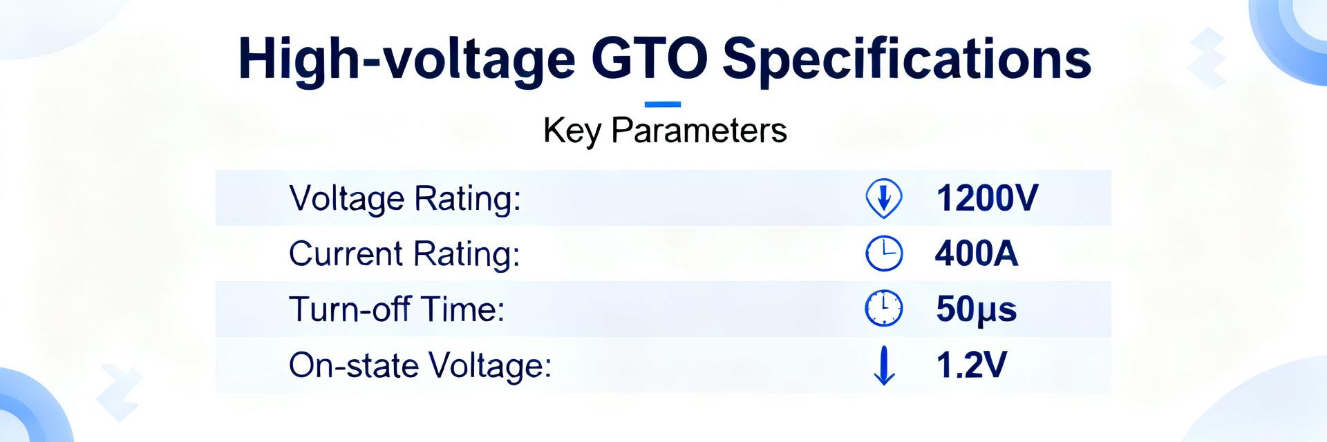
Gate-turn-off devices operate across wide ranges: blocking voltages from a few hundred volts to several kilovolts and peak currents from hundreds of amperes to kiloamperes in pulsed systems, with switching times typically tens to hundreds of microseconds. This data-driven opening frames why device ratings matter. The reader will learn how to read datasheets, compare ratings, assess dynamic performance, evaluate thermal and reliability limits, and select the right GTO for a power application. The term GTO thyristor appears here as the primary focus and the article addresses performance and specs engineers rely on.
Background: What a GTO thyristor is and where it’s used (background introduction)
Basic operating principle
A GTO enables forced turn-off by injecting reverse gate current, unlike a conventional SCR that requires current interruption externally. Key terms: anode, cathode, gate, latching current (minimum to latch on) and holding current (below which it will turn off). A schematic block diagram in a converter shows gating, commutation, and snubber networks to manage turn-off paths for the device.
Typical applications and system roles
GTOs have been common in traction drives, HVDC converters, static VAR compensators, and large motor inverters due to rugged surge handling and cost efficiency. Designers still choose GTOs where robustness and high-voltage/surge capability matter over switching speed. The table below maps application classes to typical requirements.
| Application | Voltage | Current | Freq |
|---|---|---|---|
| Traction drives | 1.2–4.5 kV | 1–6 kA | ≤1 kHz |
| HVDC valve | 2.5–4.5 kV | ≥2 kA | low |
| Large inverter | 1.2–3.3 kV | 500 A–2 kA | up to 2 kHz |
GTO thyristor electrical ratings & key specs (data analysis)
Static ratings: VDRM/VRRM, IT(AV), ITSM, I²t
Datasheets list repetitive/non-repetitive blocking voltages (VDRM/VRRM), average forward current IT(AV), non-repetitive surge current ITSM, and I²t fusing energy. Typical units: volts (V), amperes (A), kiloampere-seconds² (A²s). Derating guidance often reduces VDRM by margin and limits IT(AV) with case temperature curves; use a comparison template to track these values across parts when selecting.
| Field | Example range |
|---|---|
| VDRM/VRRM | 1.2 kV – 4.5 kV |
| IT(AV) | 100 A – 2000 A |
| ITSM (10 ms) | 1 kA – 10 kA |
| I²t (fuse) | 10² – 10⁶ A²s |
Gate characteristics and triggering thresholds
Gate drive specs define required gate current, charge and allowable reverse gate injection for turn-off. Typical drive voltages are ±10–±30 V with peak gate currents sized to meet required dI/dt control. When comparing specs, map gate charge and required turn-off current to realistic driver amplifier capability and peak sourcing/sinking performance.
Dynamic performance & switching characteristics (data analysis)
Turn-on/off times, dv/dt and di/dt behavior
Switching metrics include storage and fall times, with rise/fall measured on current and voltage waveforms. GTO switching is slower than MOSFETs/IGBTs; typical turn-off times are tens to hundreds of microseconds. dv/dt and di/dt limits drive snubber and commutation network design to prevent unintended turn-on or device stress during transition.
Switching losses, recovery behavior and thermal transients
Switching energy is given as Eon and Eoff; recovery charge during turn-off increases Eoff and thermal transients. Performance in losses is estimated by summing conduction and switching energies per cycle: Psw ≈ (Eon+Eoff)·fPWM. Use junction thermal rise per pulse to size cooling and calculate junction temperature swings for worst-case duty cycles.
Thermal, packaging & reliability considerations (method/guideline)
Thermal resistance, cooling methods and derating curves
Datasheets provide RθJC and RθJA; compute case-to-ambient heat paths and required heatsink using P·Rθ. For forced-air or liquid cooling, translate power dissipation into required airflow or coolant delta-T; follow derating curves that reduce IT(AV) with elevated case temperature. A checklist helps convert steady-state losses to cooling specs.
Packaging, mounting, and long-term reliability factors
Package type determines isolation, mounting torque, and thermal interface quality. Long-term failure modes include thermal cycling fatigue, thermal runaway, and latch-up under abnormal gate conditions. Mitigation includes controlled torque, thermal cycling testing, and sensors for case temperature and gate current monitoring to trigger protective shutdowns.
Bench testing & measurement procedures for spec verification (method/guideline)
Recommended test setups and key waveforms to capture
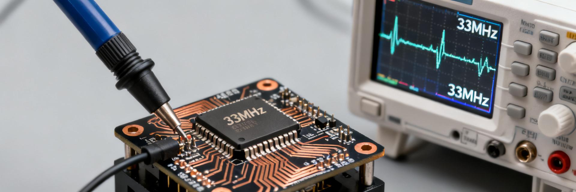
Essential lab gear: programmable power supply, high-current pulse generator, gate driver, current probes, high-voltage oscilloscope, and proper safety interlocks. Capture V-I curves, turn-off waveforms, and surge pulses; record peak values, Eon/Eoff integrals and recovery charge. Use guarded layouts to minimize parasitics affecting measurements.
Interpreting results and matching them to datasheet ratings
Validate datasheet claims by comparing measured peak currents, pulse energy, and thermal response to rated values within specified test conditions. Expect tolerances; if results deviate, troubleshoot gate drive, parasitic inductance, or thermal contact. Document test conditions thoroughly to ensure apples-to-apples comparisons.
How to choose, compare and apply a GTO thyristor (case + action)
Selection checklist for engineers
Use a compact checklist: required V/I margins, switching frequency compatibility, thermal budget and cooling method, gate drive capability and required turn-off current, surge handling (ITSM/I²t), mechanical constraints, and cost trade-offs. Prioritize VDRM headroom when transient overvoltages are likely and ITSM when fault-clearing robustness is critical.
Integration tips and system-level trade-offs
Design snubbers and commutation networks to control dv/dt and di/dt; fuse selection must consider I²t. Avoid paralleling without careful current sharing measures. For EMI, include filtering and twisted/short return paths. Evaluate cost per kilowatt and efficiency impact when documenting the final part selection in system specifications.
Summary
- How to read GTO thyristor datasheets: prioritize VDRM/VRRM, IT(AV), ITSM and I²t and compare using a consistent template to ensure required margins and derating are applied.
- Critical performance metrics: switching energies (Eon/Eoff), dv/dt and di/dt limits, and recovery charge drive snubber and driver choices and dictate thermal transient behavior.
- Thermal and reliability priorities: use Rθ values to size cooling, monitor case temperature, and plan for mechanical and thermal cycling to avoid premature failures.
- Actionable selection checklist: match V/I margins, gate-drive capability, surge handling and system-level constraints; document trade-offs and cost per kilowatt.
Frequently Asked Questions
What operating margins should I specify for GTO thyristor voltage ratings?
Specify a safe margin above expected transient peaks; a rule of thumb is 20–30% headroom on VDRM/VRRM over continuous maximum voltage to account for spikes and aging. For systems with frequent overvoltages, increase margin and ensure snubbers and surge protection are specified. Verify derating curves for case temperature influence.
How do I estimate switching losses for a chosen GTO?
Estimate switching loss per cycle as the sum Eon+Eoff from datasheet or measured tests, then multiply by switching frequency: Psw = (Eon+Eoff)·f. Add conduction loss (I²·R(on)·duty). Include recovery charge effects by measuring Eoff under representative dv/dt/di/dt and account for junction temperature dependence.
Can GTOs be paralleled safely for higher current?
Paralleling is possible but requires careful thermal matching, individual emitter resistance, and equalizing networks because slight differences in V-I slope cause current hogging. Use controlled gate drive timing and monitor device temperatures. Prefer single devices rated for the full surge if space allows, and include fast protective sensing for imbalance detection.
What are the primary long-term failure modes of a GTO thyristor and how are they mitigated?
Long-term failure modes include thermal cycling fatigue, thermal runaway, and latch-up under abnormal gate conditions. Mitigation includes controlled mounting torque, thermal cycling testing, and sensors for case temperature and gate current monitoring to trigger protective shutdowns.